Guide to 3D Machining
3D machining is a subtractive manufacturing process that uses cutting tools that follow pre-programmed cutting paths along 3 axis to create 3D parts. 3D machining is a key process in many manufacturing industries.
3D machined parts are used in aerospace, automotive, and medical devices. In this blog, you’ll learn everything about 3D machining processes like CNC machining, turning, milling, and 3D tool paths.
What Is 3D Machining?
3D machining is a manufacturing technique that produces 3 dimensional parts by removing material from a rectangular block or a cylindrical workpiece. 3D machining mostly relies on a Computer Numerical Control (CNC) micro-controller to control the movement of a tool that produces cuts on the workpiece.
3D machining requires tool movement in three axes to create complex shapes, depths and curves along a surface.
Try Prolean Now!
3D Machining: Step By Step Process
3D machining starts at the design stage, followed by automatic toolpath generation and programmable cutting. Most of the process does not require human input after the design stage, but post-processing and quality inspection require manual checks.
Some high-precision 3D machining services offer CMM technology that can accurately perform dimensional accuracy checks.
CAD Design
Create a 3D model of the part with exact dimensions and tolerances using computer-aided design software like Fusion. You can specify features, diameters, hole sizes, dimensional sizes, slots, and any kind of pockets.
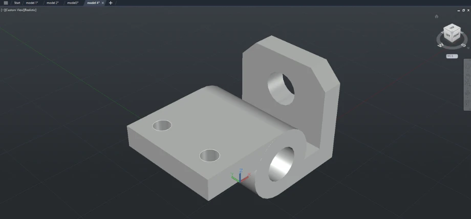
3D model of a workpiece
CAM
In the computer aided manufacturing (CAM) process, you can assign the material to your part. The purpose of CAM software like Fusion CAM is to conver the 3D part model into instructions for the 3D cutting machine.
In the CAM software, you can select tools,and machines, orient your part, and simulate the cutting process.
Generating Toolpaths
Toolpath generation is the most important step of 3D machining. The tool path is the simulated path for the cutting tool and this step translates the 3D model into instructions for the cutting machine.
Important aspects of the tool paths define if it is a roughing pass, finishing pass, material removal rate, depth of cut etc.
The CAM software outputs these commands into machine readable instructions in the form of a G-code.
CNC Machining
The generated instructions (G-code) are uploaded to a CNC machine or another 3D cutting machine according to the program.
To set up the machine, you can follow these steps
- Secure the workpiece to the CNC bed and mount the cutting tool. For example, an end mill tool on a 3-axis milling machine.
- Mount any other cutting tools if it’s a multi-tool CNC and your cutting takes advantage of tool changes.
- Calibrate the machine
- Use workpiece coordinates or global coordinates to correctly identify the workpiece position.
- Start with a rough pass
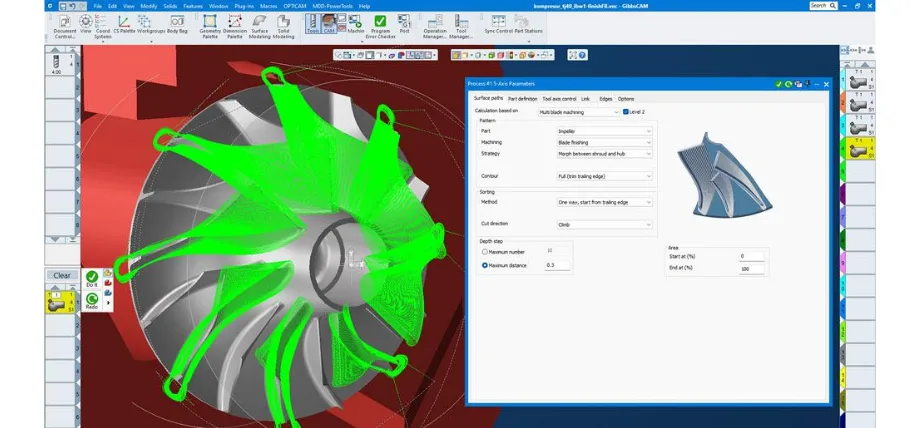
Simulating Toolpath on a Turbine
Finishing
After removing bulk material quickly, the 3D milling machine or turning machine switches to finishing passes. All tolerances, dimensional accuracy and surface finishing operations are done at this stage.
Quality Inspection
Some advanced 3D machines can perform quality control checks like accurately checking linear dimensions, curve angles, fillet radius etc. However, most of the quality control is manual and is performed after removing the part from the CNC machine.
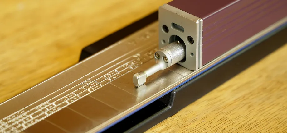
Surface Roughness Tester
Try Prolean Now!
3D Milling
3D milling is the most common type of 3D machining. The 3D milling machine has a spindle that holds the cutting tool and the tool moves along 3 axis.
- X axis – left to right translation
- Y axis – front and back tool movement
- Z axis – up and down movement of the spindle to control depth of cut
A 3D milling machine can cut flat surfaces, pockets, and contours and even create patterns on a surface. Most 3D milling cutters are flat or have a sharp corner radius.
3D milling uses a multi-tooth cutting tool that spins over the workpiece, gradually removing material layer by layer. Advanced 3D milling machines support tool rotation along two axis making it a 5-axis machining setup.
3D milling is preferred for blocks or rectangular workpieces.
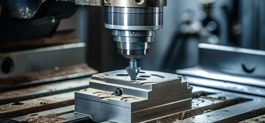
3D Milling Machine
3D Turning
3D turning is not the ideal term to describe “turning”. Turning is an operation done on a lathe machine where the workpiece is held in a chuck and rotated at high speed. The cutting tool moves in towards the workpiece.
Turning uses Z and X axis to move along the workpiece length and towards the center of the workpiece.
In turning, the tool cuts into the spinning workpiece cutting the diameter shorter and producing features on the workpiece. The advantage of turning is unmatched symmetry and precision for shapes like cones, spheres, and material handling diversity.
3-Axis Machining
3D machining can also be replaced by the term 3-axis machining. 3-axis machining refers to any machining process that uses linear X,Y and Z axis to remove material from a workpiece.
Machining here differentiates it from additive manufacturing processes like 3D printing. Machining is generally used for material removal. 3-axis machining most of the time means 3D milling and is used in woodworking, metal shaping, and engraving processes.
Some plastic and silicon machining also take advantage of 3 axis machines. These are small CNC machines with low dimensional capacity beds and can handle smaller resin or plastic pieces.
3 axis machines are easier to program than wire EDMs, 4 or 5 axis CNC machines and the only downside to 3-axis milling is cutting features like undercuts and overhangs.
2D Machining VS 3D Machining
In 2D machining, the cutting tool only uses two axes to create features on a workpiece. It is possible to create limited features with 2D machining and often the part has to be reoriented manually to cut features on different planes.
The tool moves in X and Y axis and the vertical Z axis is fixed. So there’s no depth and many times, the machine bed is raised up or down manually to adjust the depth of cut.
The cutting tool in 2D machining moves in a flat plane (think a sheet of paper) and mainly cuts profiles and outlines. 2D machines are much simpler to program and more efficient for processes like edge smoothing.
The real difference between 2D machining and 3D machining is the complexity of features they can produce. 2D machining generally produces gaskets, panels, signs and brackets.
3D machining can produce complex features and geometry accurately. 3D machining is used for molds, prototypes, and metal parts like gears and custom-machined parts. 3D machining is also more expensive than 2D machining.
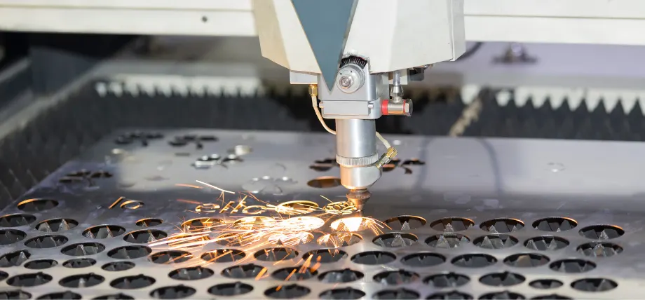
2D laser cutting machine
Choosing The Right CNC Machining
CNC machining is not limited to 2D and 3D machining. There are many other types of CNC machines that can produce parts more efficiently and are better suited for different applications.
2D Milling
2D milling operations are good for engravings, etching, and single-depth cuts. 2D machines are efficient, cheap, and require a flat part. They are ideal for surface profiling.
2D milling does not support any 3D feature and most of the time achieving 3D cutting requires manual adjustment and part orientation to cut on other faces and planes.
3-axis Milling
3-axis milling is diverse and is best for cutting complex features on rectangular workpieces. 3D milling struggles with undercuts and multi-angle cutting. It is ideal for 3D contours without extreme complexity.
4-axis Milling
4-axis milling is useful for parts that need to be cut from another side. The tool can move in 3-axis and support rotation along one of the axis. It is great for 3D parts that need symmetry and side features.
Turn-Milling
Turn-milling or turn-mill is the most advanced machining and it is specifically designed for parts that need turning and milling in a single operation. It can switch between tools, rotate the workpiece and the tool, and is ideal for cutting round features and detailed profiles in a workpiece.
Turn-milling is extremely expensive and requires experienced programming and CAM processing.
High Precision 3D Machinnig Service
Prolean-tech offers 3D machining of metal parts in various industries including aerospace, medical, automotive, electronics, and many more. We offer tailored CNC machining solutions for your custom parts.
Reach us today for a free quote.
3D Milling Service
Conclusion
3D machining is not a new concept in precision machining and has been around for decades. The newest machining technology is a development of 3D machining and uses 4-axis, 5 axis and up to 7-axis. The most common 3D machining processes involve 3D milling and it can produce many intricate designs but struggles with hidden features and undercuts.
Overall, 3D machining offers a quick solution to highly precise machining of workpieces and is capable of turning CAD designs to finished products.
FAQ
-
What is 3D machining?
3D machining involves the use of 3 axis for removing material from a workpiece. The tool moves in X (left to right), Y axis (inward and outward) and Z axis (up and down).
-
What is the difference between CNC and 3dp?
The fundamental difference between CNC and 3DP (3d printing) is that CNC is subtractive and 3D printing is additive.
-
Is CNC 2D or 3D?
CNC usually operates in 3 axis (X, Y and Z). Although there is an option to only cut in 2D by fixing one of the axis.
-
Can CNC do 3D?
CNC can do 3D cutting and machining. CNC routers are capable of performing 3D cuts on wood and plastics. CNC machines have higher spindle speeds and tool capabilities that allow them to cut on tough metals.

0 Comments