
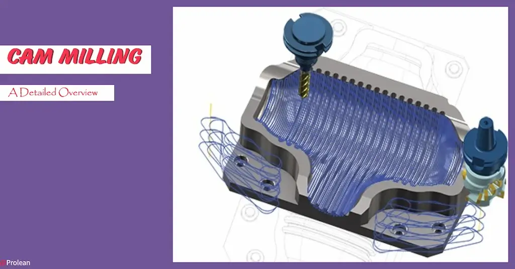
“Computer-aided manufacturing (CAM) transforms digital designs into precise physical parts with exceptional accuracy and efficiency. It enables the production of complex geometries with high tolerances by automating the milling process”
Computer Aid Manufacturing(CAM) is the classical way of subtractive manufacturing. It automates the material removal process using computer software and CNC machines. The CAM technology is compatible with all types of machining processes. CAM Milling is the machining process where computer software converts the CAD models of desired parts into machine-readable digital instructions. Then, a multi-point rotting tool follows those instructions to shape the stationary workpiece.
You can simply understand the CAM with a computer tool that generates your design’s G and M codes. Later, these codes run the machine and cutter movement.
This article will discuss the use of computer-aid manufacturing(CAM) technology in CNC Milling operations. How does it impact the precision and overall efficiency of complex parts manufacturing?
What is Computer Aid Manufacturing (CAM) and CAM Milling?
In traditional machining, operators manually move the spindle or tool using mechanical levers, gears, or other similar mechanism. It not only limits the production speed and precision but also the complex geometrical items. On the other hand, CAM manufacturing automates the positioning, tool movement, alignment, positioning, and speed. It is done by converting the CAD design into the set of instructions for the machine using software like Fusion 360, MasterCAM, PTC Creo, etc.
CAM milling parts
Next, what is CAM Milling? It is a sub-type of CAM manufacturing that mainly deals with CNC milling techniques, where a spindle moves with an attached rotating cutter across the stationary work according to CAM (or G code) instructions.
The history of CAM milling is associated with Numerical Control(NC) Manufacturing, Dr. Patrick first used numerical programs to machine the workpieces in 1974. Later, the CAM becomes an essential aspect of CNC manufacturing after integration with Compuetr-Aid Design (CAD) Software after 1980.
Try Prolean Now!
What is Computer Aid Manufacturing (CAM) and CAM Milling?
In traditional machining, operators manually move the spindle or tool using mechanical levers, gears, or other similar mechanism. It not only limits the production speed and precision but also the complex geometrical items. On the other hand, CAM manufacturing automates the positioning, tool movement, alignment, positioning, and speed. It is done by converting the CAD design into the set of instructions for the machine using software like Fusion 360, MasterCAM, PTC Creo, etc.
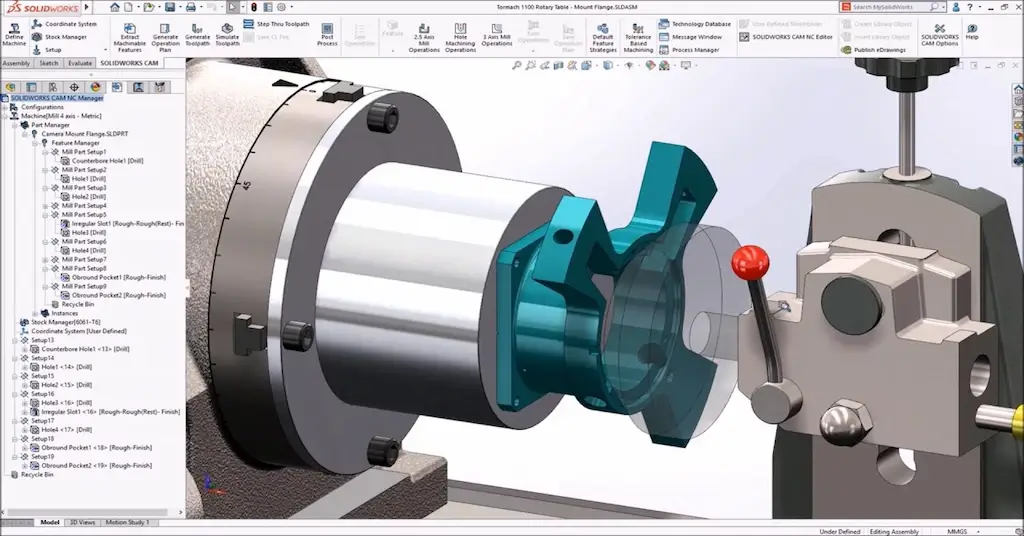
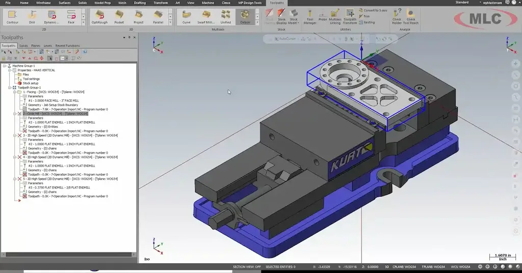
CAM milling simulation
Next, what is CAM Milling? It is a sub-type of CAM manufacturing that mainly deals with CNC milling techniques, where a spindle moves with an attached rotating cutter across the stationary work according to CAM (or G code) instructions.
The history of CAM milling is associated with Numerical Control(NC) Manufacturing, Dr. Patrick first used numerical programs to machine the workpieces in 1974. Later, the CAM becomes an essential aspect of CNC manufacturing after integration with Compuetr-Aid Design (CAD) Software after 1980.
How Does CAM Milling Work?
The CAM milling is done according to the capability of machining equipment, eg, how many milling axis does it have? So, the CAM instructions depend on whether the machine can move the spindle along 3, 4, 5, or even further axes.
Step 1: 3D Modeling of Milling Part
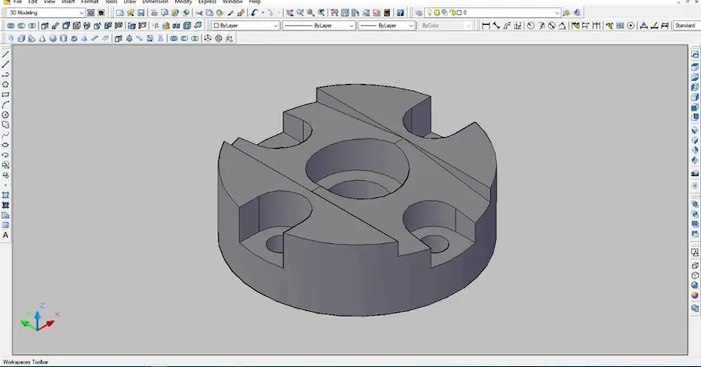
3D design in AutoCAD
It is not exactly part of CAM processing, but a detailed and compatible design is what defines the end requirement of the desired part. Engineers run CAM software like Mastercam accordingly to generate the instructions, which can achieve that.
During the design phase, you need to consider the tool access, precision capability, and other various aspects of the available machining equipment and tooling. A 3D model must clearly illustrate the features, dimensions, milling planes, hidden surfaces, etc. Additionally, choosing compatible CAD software is also essential.
Other technical considerations are equally important in design based on what kind of geometries the required part has. For example, the depth-to-width ratio for a channel, minimum wall thickness, depth cavities, etc.
Step 2: CAD to CAM Transition
Preparing CAM File with instructions
Next, choose the suitable CAM software. Often, CAD software like Fusion 360 and SolidWorks have CAM integrations that allow to generation of the toolpath and a corresponding instructions file. On the other hand, you can upload your design into CAM software like MasterCAM and CAMworks and process it there.
These software typically interpret 3D file formats like DWG, DXF, IGES, SLDPRT, STEP, STL, and many more.
CAM software can simulate the tool path and find the optimal path, variables, and operations sequence. Meanwhile, a programmer can add and customize the codes based on specific milling requirements.
| Tranition Mechanism | Description |
| Model Interpretation | CAM software processes 3D model geometry into points, lines, and curves to recognize features like holes, pockets, irregular contours, etc. |
| Toolpath Generation | Next, it computes efficient toolpaths based on geometry and cutting strategies (e.g., zig-zag, contouring). |
| Post-Processing | Converts toolpaths into G-code (for movement) and M-code (for machine control) specific to the CNC machine. |
| Example | It Interprets a STEP file with pocket dimensions and surface curves. G01 X100 Y200 F150 for linear movement, M03 S500 to start spindle at 500 RPM. |
Step 3: Execution of CAM Instructions
The workpiece and tools are attached to the machine and positioned in the (0,0,0) reference. The operator sets the cutter teeth just above the surface of the initial milling point. Then, The machine starts to follow the G and M -codes of the CAM file. G-code dictates the tool path, whereas M-code controls the auxiliary variable. The tool continues to remove the material until the finished part is achieved. Here, the CAM milling also leaves a smoother surface finish compared to conventional milling operations.
What Are the CAM Milling Applications?
CAM milling automates CNC milling operations, such as cutting, drilling, contouring, threading, taping, boring, etc. So, various industries use this technology to manufacture complex components and products with high precision. Basically, CAM-integrated CNC milling applications are more common in those areas where precision and complex features are critical requirements for performance.
| Industry | Why Use? | Application Examples |
| Automotive | – High precision – Fast prototyping – Repeatability | – Engine blocks – Bracket – Suspension components |
| Aerospace | – Lightweight materials – Tight tolerances – Complex geometries | – Turbine blades – Fuselage parts – Landing gear components |
| Medical Devices | – Biocompatibility – Precision for patient-specific components | – Surgical instruments – Orthopedic implants – Dental components |
| Electronics | – Miniaturization – High accuracy for circuit integration – Heat dissipation | – PCB enclosures – Heat sinks – Connectors |
| Defense | – High-strength materials – Precision in mission-critical components | – Weapon system parts – Armored vehicle components – Aerospace fittings |
What Are the Advantages of CAM Milling?
The following are the key CAM milling advantages;
Complex Parts and Components
The CAM Miling produces intricate geometries for aerospace, medical, automotive, and other various industries. The software can make the instructions for complex tooling paths and multi-axis (3, 4, or 5) milling equipment can execute advanced machining techniques based on those instructions, face milling, pocketing, drilling, boring, slot milling, and contour milling are a few to name.
Reduced Cycle Time
The CAM instructions automate the milling processes, which makes the production cycle much faster. Additionally, it also lowers the machining downtime. Advanced milling can also have an Automatic Tool Changer mechanism, further improving the production speed.
Cost Benefit
Automation significantly minimizes human intervention, so the labor cost decreases. Additionally, the milling speed rescues the per-part manufacturing cost.
Precision Machining
The CAM-integrated milling operation can archive a tolerance of 0.005″ or even lower. Consequently, this tolerance is also achievable throughout the batches with excellent repeatability.
Reduced Material Waste
As previously said, CAM milling follows the optimal machining path, reducing material waste. Unlike manual lathes, you don’t need to go from large to finer chip sizes to obtain accuracy.
Try Prolean Now!
Conclusion
CAM milling converts highly accurate and complex deings by executing the G and M-codes generated by CAM software. First, the software simulates the CAD design for optimal tool parts for material removal. Then, it generates those codes to follow that path by milling cutters.
Furthermore, the expertise of engineers and available milling equipment also impact the results of CAM milling. The more experienced engineers and higher axes capability of milling machines can only handle the precision-sensitive applications. If you are looking for CAM-milled parts, our CNC milling service is ready to cater to your needs. At ProleanTech, we first simulate the CAD for the tool path and generate accurate instructions before executing the milling operations. So, we can provide the parts that exceed your expectations.
FAQs
How does Computer-Aided Manufacturing (CAM) enhance accuracy and precision?
CAM improves accuracy by automating tool paths and minimizing human error. It allows precise control over tool path and movements for accurate and consistent parts/
Is CAM Milling Expensive?
CAM milling can be costly due to the initial investment in software and CNC machines. However, it offers long-term savings through higher production efficiency, reduced waste, and lower labor costs.
What kind of geometries can be made with CNC Milling?
CNC milling can produce complex geometries, including 3D contours, pockets, internal cavities, slots, holes, and intricate curves.
Are CNC and CAM Similar?
CNC and CAM are related but not identical. CNC (Computer Numerical Control) refers to the automated control of machines, whereas CAM (Computer-Aided Manufacturing) involves software that creates the tool paths and instructions for CNC machining processes.
0 Comments