
Geometric Dimensioning and Tolerancing (GD&T) establishes a system to provide precise design details and communications. It allows engineers and manufacturers to handle dimensional variations and geometrical irregularities. The US military began developing GD&T concepts during the 1940s, but the ASME Y14.5 standard was first published in 1966, formalizing the system. GD&T developed over time to become a universal industry standard. The updated 2018 version of the ASME Y14.5 standard serves as a guide for application. GD&T symbols and charts verify the appropriate assembly of manufactured parts. The system outlines which dimensional deviations are permissible and the procedures for their measurement. Besides, it allows design manufacturers to attain better accuracy results in all stages of production, as the design intent becomes more evident in shared information. Let’s walk through geometrical dimensioning and tolerance from an in-depth look.
What Is Geometric Dimensioning and Tolerancing (GD&T)?
GD&T Basics
Geometric Dimensioning and Tolerancing (GD&T) is a method to define dimension and tolerance compared to standard plus/minus approaches. Complete CAD models possess no defects, but real-world manufacturing results in minor differences. GD&T manages variations in manufacturing, which ensures that products maintain their designed specifications.
Moreover, it dominates two main features, including an established design language. The method enables better communication between design, manufacturing, and inspection teams. Besides, it allows users to determine the maximum possible mating limit, which ensures proper component interaction. The system establishes reliability and minimizes production errors from start to end.
In addition, the GD&T study enables better team cooperation, which leads to the creation of superior-quality components. It demonstrates production repeatability and correct assembly of qualified parts. Manufacturing processes become smoother through the implementation of appropriate technology together with reliable partnerships, which minimize expenses and promote superior accuracy during custom manufacturing operations.
How GD&T Impacts CNC Machining Tolerances?
GD&T In CNC Machining
CNC machining tolerances in GD&T identify permissible dimension fluctuations of manufactured parts. The variations exist in dimensions but remain invisible to routine human observation and strongly impact the part functionality. All CNC machined parts show flat and straight appearances but contain minor imperfections throughout their entire cross-sectional area. Manufacturers allow minor imperfections in dimensions if they fall within set tolerance ranges since every part exhibits slight variations.
The engineering process should expand tolerances as far as possible without affecting product functionality. Reduced dimensions in tolerances trigger increased expenses for production machines, quality checks, and manufacturing tools. The best way to limit manufacturing expenses is by making tolerances wide since tight tolerances must remain for essential applications only. The dimensions achievable through CNC mills typically span from 0.005 inches, which is higher than corresponding to the thickness of human hair (~0.003 inches). Although precise tolerances can be manufactured, they are not required for every application. At prolean tech, our cnc precision machining services can achieve Tolerances down to ±0.0002″ (0.005mm).
Try Prolean Now!
Geometric Dimensioning and Tolerancing Examples: Datums Features in GD&T
Datum in GD&T
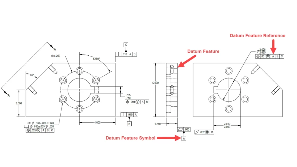
The Datum Reference Frame (DRF) functions as a coordinate system throughout GD&T to specify the features and tolerances of a part. A reference frame system validates the correct production and quality control of manufactured parts. All dimensional specifications and geometric features in the design reference (DRF) represent the final assembly configuration.
A DFR constrains a part’s Six Degrees of Freedom (DOF) through 3 translational measures and 3 rotational parameters to establish a consistent measurement framework. The processing and measuring of the part requires proper limitation of these Degrees of Freedom. The main difference in GD&T exists between datums and datum features. The DRF contains theoretical elements known as datums and actual physical features of the part named datum features. The functional requirements of a part entirely depend on imperfect datum features.
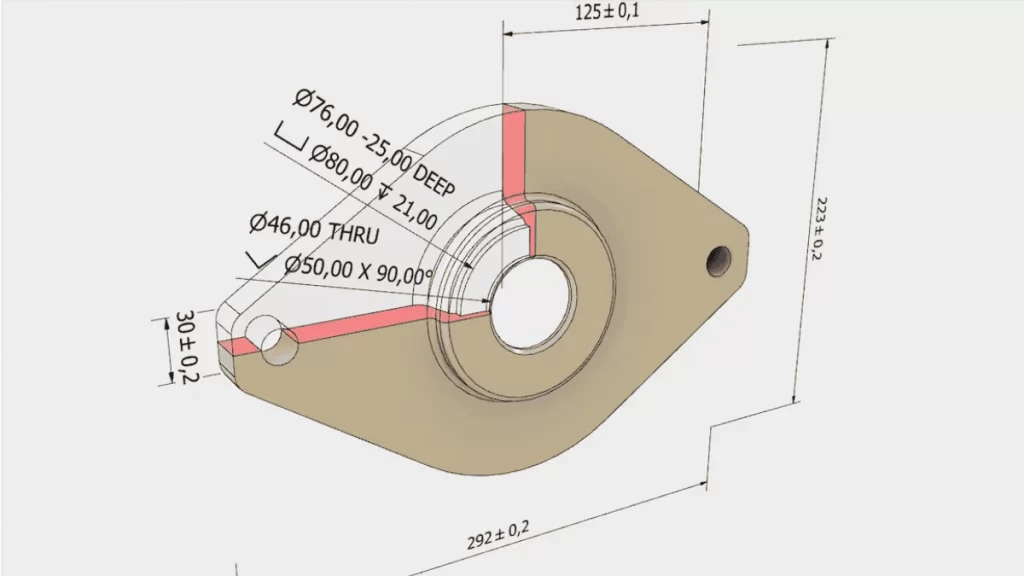
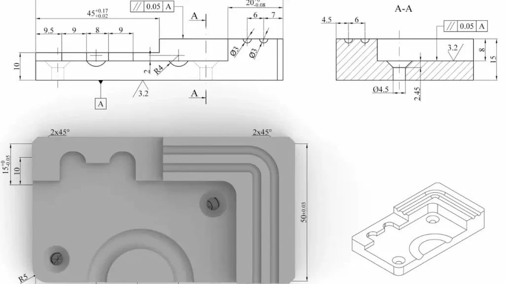
Feature of Size
Geometric Dimensioning and Tolerancing Chart
Geometric shapes that require dimension measurements, including length, angle, and height, constitute the classification of size features. Using callipers to measure dimensions inside or around the part indicates that the feature qualifies as a Feature of Size. Tolerances can be added to these features, yet orientation tolerances precisely control how features’ axes and midplanes relate to datums. The character of the feature counts as a Feature of Size only when callipers serve for its measurement instead of probes.
GD&T Tolerancing Guidelines
GD&T Tolerancing
Clear product communication is the main priority when drawing engineering specifications, yet the addition of redundant details should be avoided. The following group of rules provides practical guidance.
- Drawing clarity remains the core aspect that needs the highest focus. Place all dimensions and tolerances beyond the part’s boundary area with their application to visible lines. The drawing must follow a one-way reading path. At the same time, users will receive an immediate understanding of the part usage, and dimensions should be organized or arranged according to a particular pattern with sufficient blank space to keep the document easy to understand.
- Make sure to choose tolerance levels that are just as loose as the essential part functionality requires. Manufacturing, inspection work, and tooling become more expensive when tolerances get tighter. Designing with more considerable allowable variations will lead to cost savings.
- A general tolerance should be added to the drawing title block for all dimensions. Drawing-specific tolerances take precedence over general tolerance. Therefore, only state it again when it affects specific dimension measurements.
- The first step should be to address the tolerances of the most crucial functional features followed by their relationship. The process should start with addressing critical functional elements before moving forward with the rest of the drawing content.
- Engineers should handle manufacturing specifications by excluding them from engineering drawings. They must determine the manufacturing processes to create the part. The simplified drawing structure results from this practice, which also prevents drawing complexity.
- Drawings should exclude 90-degree angle specifications because this standard angle remains implicit unless engineers need to address exceptional angles.
- The drawing dimensions and manufacturing tolerances are assumed to be valid under 20°C with 101.3 kPa pressure conditions unless alternative parameters are explicitly mentioned. Include special notes when the designed part functions in settings unlike those specified by the drawing. (Read more about tolerance stacking)
Try Prolean Now!
GD&T Symbols and Controls
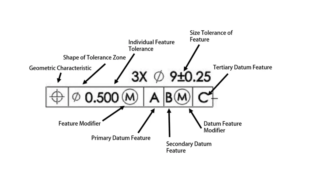
GD&T Symbols
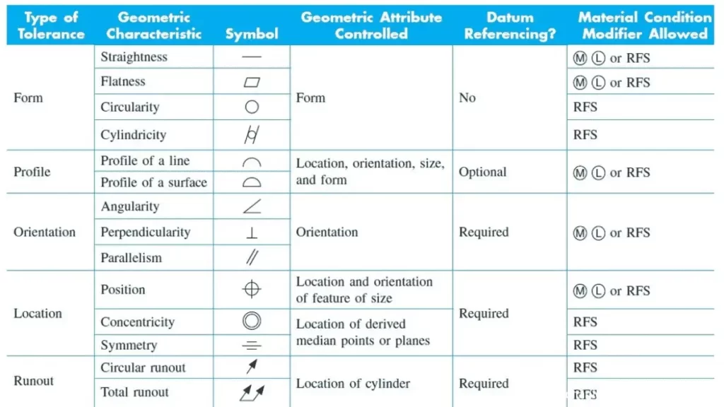
GD&T symbols are used to define specific features of the part. Below is a summary of the most commonly used symbols and their meanings:
| Symbol | Description | Control Type |
| Straightness | Controls the straightness of a line or axis. | Form |
| Flatness | Ensures a flat surface by controlling the variation between the highest and lowest points. | Form |
| Circularity (Roundness) | Controls the roundness of a feature, ensuring it is consistently circular. | Form |
| Cylindricity | Ensures a feature is cylindrical, controlling straightness, roundness, and taper. | Form |
| Line Profile | Controls the two-dimensional profile of a feature about its ideal shape. | Profile |
| Surface Profile | Controls the three-dimensional profile of a feature, ensuring the surface falls between two offset curves. | Profile |
| Angularity | Ensures flatness at an angle to a datum, defined by two reference planes. | Orientation |
| Perpendicularity | Ensures flatness at 90 degrees to a datum defined between two perfect planes. | Orientation |
| Parallelism | Ensures a feature remains parallel to a datum, defined with a cylindrical tolerance zone for axes. | Orientation |
| Position | Defines the exact location of a feature relative to others or to a datum. | Location |
| Concentricity | Ensures that a feature’s axis is aligned with a datum’s axis. | Location |
| Symmetry | Ensures that non-cylindrical parts are symmetrical across a datum plane. | Location |
| Circular Runout | Measures variation (wobble) around a rotational axis, typically used for ball-bearing mounted parts. | Runout |
| Total Runout | Measures variation across an entire surface, including straightness, angularity, and profile. | Runout |
GD&T Example Case Study
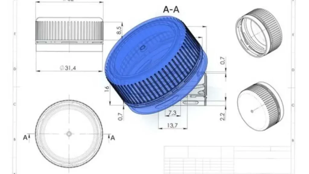
GD&T Tolerancing for Plastic Bottle Caps
The present case study defines how SolidWorks employs GD&T to create 50,000 bottle caps produced through injection molding. The manufacturing objective requires the bottle caps to have a proper fit and consistent resistance level when attached to the bottles. The application of tolerances is critical in minimizing dimensional variations in the cap dimensions.
Bottle Cap Design Objectives
The bottle cap thread requires a dimension of 36.95 mm, with a tolerance range of +/-.010 mm. The inner diameter of the cap should range between 36.985mm(lower limit), and 37.065mm(upper limit), while the optimal dimension stands at 37.0 mm. A hole for the 4 mm axle exists in the cap, while the tolerance for this hole reaches 0.13 mm. A hole size of 3.85 mm meets the fitting requirements while drilled to a precise 4.00 mm.
To control dimensions properly, we must establish a datum reference. The inner cylindrical part of the cap functions as the primary reference surface because bottle fitting depends on it. The mounting surface of the cap requires the flat top portion as its secondary datum.
Solution
SolidWorks users achieve GD&T application by selecting features and datums, which can be found through DimXpert > Auto Dimension Scheme. The software program produces tolerances in addition to GD&T symbols based on predefined specifications. Features with unequal limits receive selected tolerance types, either ‘bilateral’ or ‘limit.’
The addition of tolerances to the drawing happens through importing annotations from the FeatureManager alongside enabling the ‘DimXpert annotations’ option for complete drawing clarity. (Get more insights on Press Fit Tolerance)
Summary
This guide explains how Geometric Dimensioning and Tolerancing (GD&T) maintains exact control of part dimensions and design specifications. A few symbols used with datum features and feature control frames in GD&T improve production drawing clarity and maintain uniformity within product assemblies.
Design Companies who adopt GD&T determine optimized tolerance levels, which they customize based on their selected production procedures while accounting for process-generated variation. At Prolean Tech, we offer precision cnc machining services. Our team utilizes digital manufacturing tools, mainly advanced CNC machining and 3D printing, to optimize production operations. The implementation of GD&T allows us to lower expenses and shorten manufacturing times while delivering products quickly and maintaining our market competitiveness.
FAQ’s
Q1: What are the 5 categories of GD&T?
The 5 categories of GD&T are
- Form,
- Orientation,
- Location,
- Runout, and
- Profile.
Q2: What’s the difference between GD&T and traditional coordinate tolerancing?
GD&T provides more detailed and flexible tolerance limits. It considers the part’s geometry, while traditional coordinate tolerancing only focuses on specific measurements from a fixed point.
Q3: How do I apply GD&T to a CNC-machined shaft?
You can apply GD&T by specifying the relevant geometric features (e.g., straightness, perpendicularity) on the shaft drawing and including the appropriate symbols for each tolerance.
Q4: Can GD&T reduce manufacturing costs?
Yes, GD&T helps reduce manufacturing costs by providing clear, precise tolerances. So, it minimizes material waste, machining errors, and costly rework.
Q5: What tools verify GD&T compliance?
Tools like callipers, micrometres, height gauges, CMM (coordinate measuring machines), and optical comparators can verify GD&T compliance.
Q6: Why choose a GD&T-certified CNC service provider?
A GD&T-certified CNC provider makes sure of the accurate interpretation and application of GD&T standards. This leads to better part quality, fewer mistakes, and lower production costs.

0 Comments